Working since 2010
We are Qzone
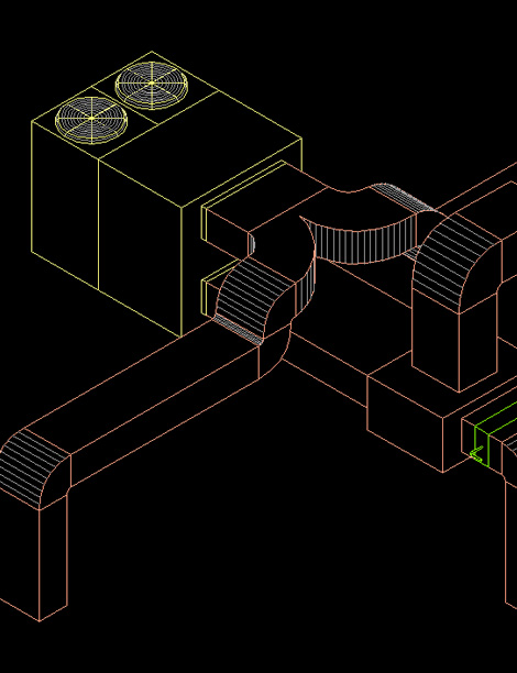
Duct Designing in AutocadWe have team of highly qualified designer for duct designing, we use technical method for designing the same as per air velocity in CFM/CMH.
Key aspects of duct design in AutoCAD
Effective duct design in AutoCAD involves several key steps, including gathering necessary information like building layout and HVAC load calculations, and setting up the drawing with appropriate units and scales.
The process involves drawing the building layout and designing the ductwork routes with correct dimensions and configurations. Essential fittings and accessories, such as elbows and dampers, are added to ensure proper airflow. Labeling and annotating components are important for clarity during installation. Designers also create sections and elevations to visualize duct placement and check for interferences with other building elements.
Preparing documentation, such as comprehensive ductwork drawings, and coordinating with other disciplines are also vital. AutoCAD offers both 2D and 3D capabilities for detailed representation. Automated features, including automatic fitting insertion and routing preference settings, streamline the design process. Defining HVAC system settings and using the system browser and analysis tools help manage components and optimize designs.
Importance
Duct design in AutoCAD is crucial for creating accurate and efficient HVAC systems. It facilitates visualization, planning, and implementation of ductwork layouts, ensuring compliance with design specifications and building codes.
© Copyright QZone Technical Services All Right Reserved
